Washer/Dryer End-of-Cycle Monitor
My old Kenmore Front-loading washer finally died after 16 years (bearing went), so I needed to replace it (and figured replacing the dryer at the same time made sense, since it would also be close to the point of age-related failure).
I did my usual technique of research: Consumer Reports, Amazon user reviews, etc. and settled on a Samsung Washer/Gas Dryer combo. As is usual with the Consumer Report recommendations, the absolute Top-of-the-Line models have extra frills that actually reduce reliability. I didn’t need a Touch-Screen Interface. But what I lost going to the second-from-the-top models was End-of-Cycle indications. The washer and dryer themselves will play little tunes, but they’re in the garage, with a heavy fire-rated door, and so I just don’t hear them in the main areas of the house.
So inspiration hit me: why not tie them into the house Home Automation system? It shouldn’t be that hard — just need to figure out when they’re drawing power, and then when they stop drawing power, and that’s the End-of-Cycle.
I ordered some Current Transformers, sliced open some Power-Strip-Saver 1-foot extension cords so I could put the current transformers around just the Hot lead, and created a conditioning circuit that feeds a 10-bit Analog-to-Digital converter that is monitored by a Raspberry Pi.
I happened to be on a Chinese website that had backlit 20×4 LCD displays for $8 (with an I2C interface backpack), so I snagged one. I figured it would be great to run the Raspberry Pi “headless” but be able to display status information on both the Washer and the Dryer.
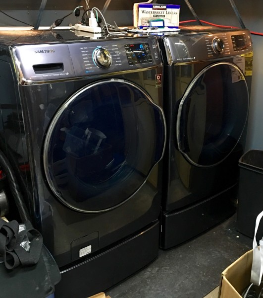
So here’s what the washer (left) and dryer look like. They have an insane capacity, like 5.6 cubic feet, enough for 26 towels in one load. They also have a ton of very sophisticated modes, like “Allergens” to really get stuff clean, and “Activewear” to wash your spandex gym clothes without destroying them. I also got the matching pedestals because, with my arthritic knees, bending over to get stuff in and out of the washer and dryer was damn painful at times
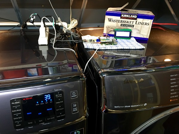
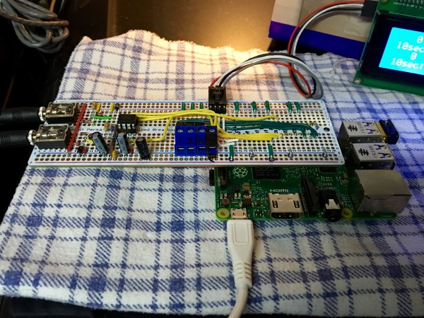
Here’s the experimental setup on top. The power strip has the two mini-extensions with the current transformers plugged into it, as well as the power supply for the Raspberry Pi. In the middle is the Interface Board on top of the Pi (which has a WiFi dongle plugged into one of the USB ports), and the 4×20 display is propped against the box of trashcan liners. I’ll put it all in a real case shortly.
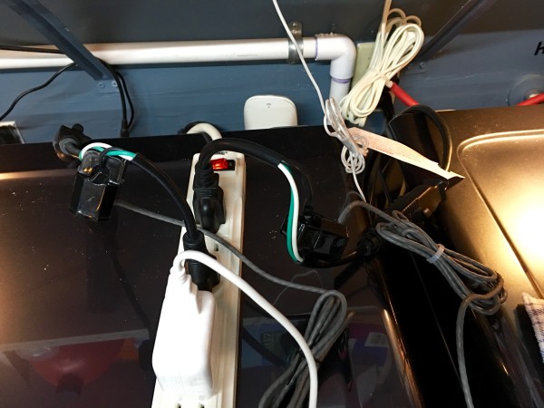
You can see the mini-extension cords partially stripped of their outer covering, so the current transformers can go around just the Hot lead.
Here’s the interface board on top of the Pi. The WiFi dongle is a mini (because the distance to my access point is not that far). The terminal strips are because I was thinking of running a wire to the three motion detectors of the alarm system that came with the house down so I could monitor them. The current transformers have 1/8″ stereo plugs, and they go into the jacks on the far left of the interface board.
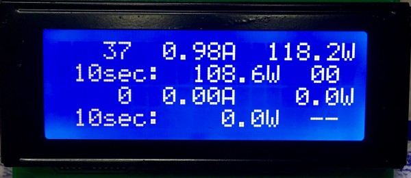
The status display with just the washer running. The ADC is running off of 3.3V, and is 10-bit, i.e. maximum count of 1023. So each count of the ADC is 3.22mV.
The current transformers are 2000:1. By Ohm’s law, E = I * R. With a “burden” resistor of 330Ω, that would translate to 1A ÷ 2000 = 2mA. 2mA × 330Ω = 0.66V Where things get complicated is that the output from the current transformers is AC, and we full-wave rectify it to DC, so you get 1/√ 2 and other weirdness.
The actual measured voltage tends to be more like 115VAC than the desired 120VAC. On the dryer, 1358W was 11.84A and was 442 ADC counts. On the washer, 1361W was 11.87A and was 449 ADC counts. So basically it’s 0.0268A/count on the dryer, and 0.0264A/count on the washer. I split the difference, and use:
- ADCtoAmps = 0.02661192797 # multiply ADC by this to get current in Amps
- ADCtoWatts = 3.1934313558 # multiply ADC by this to get power in Watts
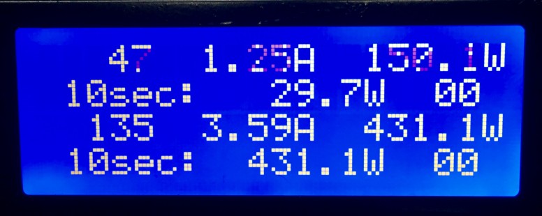
The display (washer info on top, dryer below) shows the current ADC reading, what that translates to in Amp, what that translates to in Watts, and then we average the readings over a 10-second period to produce an average that we use for control.
The last piece displayed is the State Machine counter. 00 means the device is consuming power. If we suddenly switch to 00, we send a “<device> STARTED” message to the house status display. If the 10-second average of the power consumed drops below a threshold (3W for the washer, 200W for the dryer), we increment the State Machine counter. If it hits a threshold (7 for the washer, 2 for the dryer), we are deemed to have “ended” the cycle, and we call the house Home Automation controller saying so.
Obviously, we can track both at once.
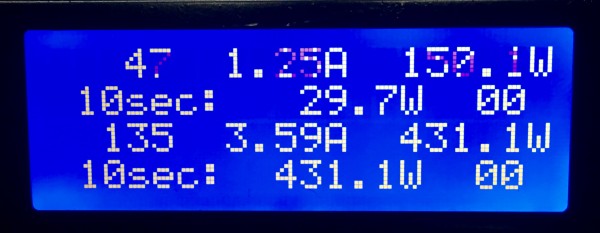
We use the different thresholds because the machines behave very differently. The dryer just keeps chugging along at 430W spinning the drum when it’s running. (It could consumer 1000W more if it engages the Steam mode.) The washer starts, stops, waits, fills, drains, and spins, with long periods of low or no activity, so we have a much lower threshold, and a much longer wait to judge it’s really done.
The Home Automation system flashes Hue lights in the Living Room and the Bedroom, blue for the washer and green for the dryer. It also displays a message on the British Flag status displays in the Living Room, just to drive it home.


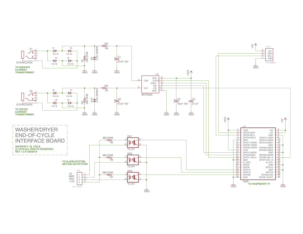
So here is the schematic of the Interface Board. It’s pretty straightforward. I did it all on Protoboard that has layout that matches the solderless breadboards. If it were Mission Critical or I was doing a lot of them I’d go ahead and make a PCB.
I hit a bunch of weird hardware issues, which I was finally able to troubleshoot with this nifty USB Oscilloscope/Logic Analyzer. It’s able to decode and display SPI (as well as I2C and Serial) which is especially handy. And all for $25, with performance rivaling dedicated units in the $1,500 – $5,000 range. For an occasional experimenter like me, this thing is damn handy!
Parts mentioned:
Raspberry Pi 2 – Model B – ARMv7 with 1G RAM
Quad Alphanumeric Display – Blue 0.54″ Digits w/ I2C Backpack
IDC Breakout Helper – 2×20 (40 pin)
Adafruit Perma-Proto Full-sized Breadboard PCB – Single
1N4148 Signal Diode – 10 pack
0.1uF ceramic capacitors – 10 pack
47uF 25V Electrolytic Capacitors – Pack of 10
Analog to Digital Converter – MCP3002
Non-Invasive Current Sensor – 30A
IIC I2C 2004 204 20 x 4 Character LCD Display Module Blue
LHT00SU1 Virtual Oscilloscope Logic Analyzer I2C SPI CAN Uart